
The blow molding machine uses the MOOG wall thickness control system to ensure a more uniform and accurate wall thickness.
So, how should the core position of the MOOG controller be set accurately?
Next, go straight to the topic.
The core clearance position sensor is used to detect the core position (ie wall thickness hydraulic cylinder piston position). The effective detection stroke of the core clearance position sensor should be slightly larger than the stroke of the wall thickness hydraulic cylinder. And when installed, the stroke of the two can correspond in the actual space position, that is, when the wall thickness hydraulic cylinder piston moves to the end of the hydraulic cylinder stroke, the core clearance position sensor should also move to the endpoint corresponding to the corresponding stroke. That is, the hydraulic cylinder stroke must be within the effective range of the core clearance position sensor detection stroke.
If the installation is incorrect, it may cause the core clearance position sensor to incorrectly detect the wall thickness of the hydraulic cylinder piston or cause damage to parts such as the core clearance position sensor.
The basic settings for the core clearance position sensor include zero (ZERO) and range (SPAN).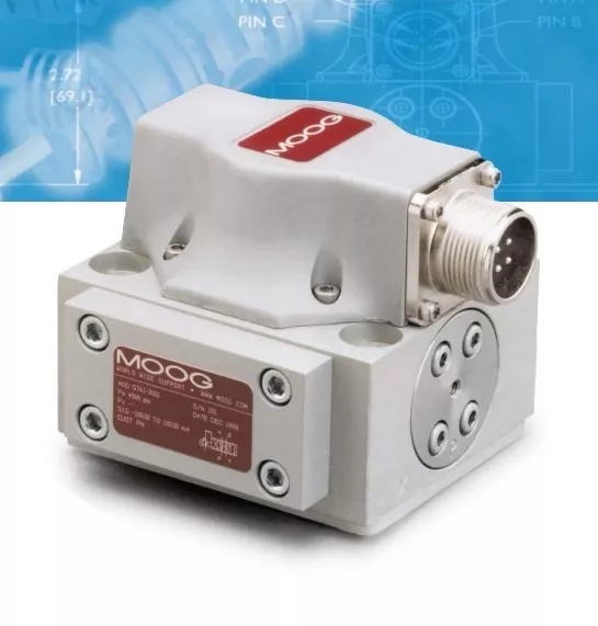
Zero-point (ZERO) refers to the value of the sensor voltage when the wall thickness hydraulic cylinder is at the starting position of the stroke.
The range (SPAN) usually refers to the sensor voltage value of the wall thickness hydraulic cylinder at the end position of the stroke.
The basic setting of the core clearance position sensor is very important for the normal operation of the wall thickness control system and is the basic data of the wall thickness control system. It is necessary to appropriately reduce the pressure of the oil source during the setting. During the setting process, it is necessary to repeatedly correct the positional correspondence between the sensor, the cylinder piston, and the die clearance to ensure accurate correspondence and prevent mechanical or electrical parts due to accidental failure, damage.
Generally speaking, when the hydraulic cylinder piston is at zero points, the die clearance cannot be zero, and a certain safety clearance must be ensured. At the same time, the sensor detection rod is kept at a certain distance from the end of the stroke, so as to ensure that the entire system is in a safe state. If the die is completely sealed (the gap is zero), accidental failure of the electrical components may result in serious damage to the mechanical parts such as the die, the extruder screw barrel, and the gearbox. The die clearance at zero (ZERO) can be adjusted by the manual wall thickness adjustment mechanism to achieve the clearance required for production.
After the basic setting of the core clearance position sensor is completed, in general, there is no need to reset the die when the die is replaced, unless the reference surface of the sensor detection and installation changes.
After this setting is completed, the basic setting of the wall thickness controller of the continuous blow molding machine is over. By adjusting the pressure of the servo-hydraulic oil source to the normal working pressure, the wall thickness control system can enter the working state.
The above is the correct setting method for the core clearance of the MOOG controller.
You actually make it seem so easy with your presentation but
I find this topic to be actually something that I think I would never understand.
It seems too complex and very broad for me. I am looking
forward for your next post, I will try to get the hang of it!