
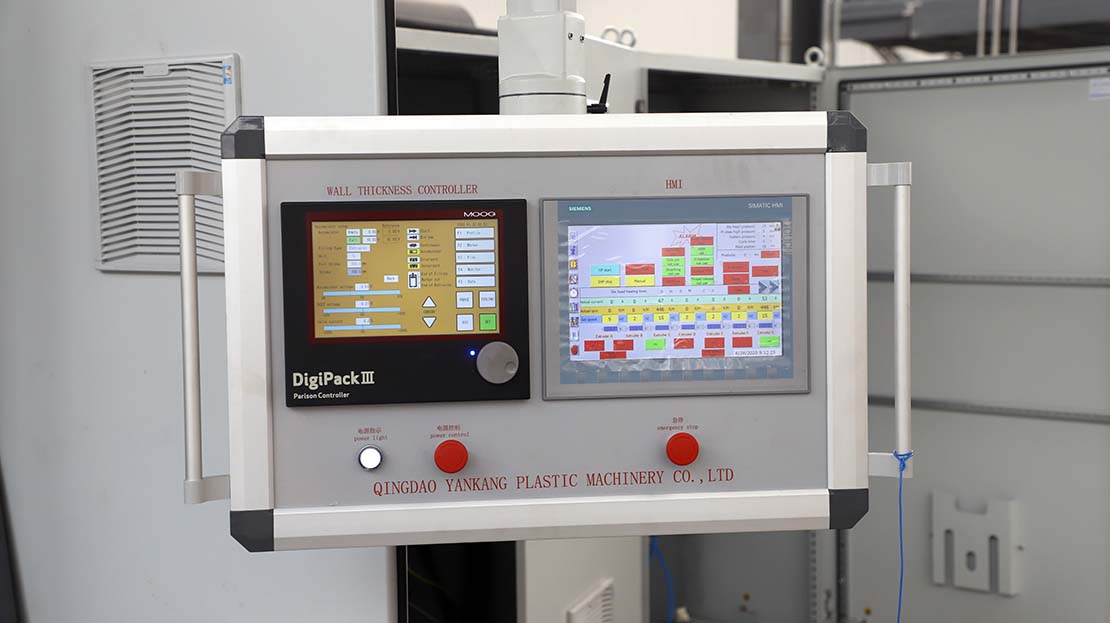
The operation profile of the MOOG parison wall thickness controller is the focus of this post.
For hollow products, controlling the thickness of the parison wall is of great significance to improve product quality and reduce costs.
If the product is not effectively controlled during the blowing process, uneven thickness will appear after cooling. The stress of the parison wall with uneven thickness is also different. Thin parts are easily broken.
Using the parison wall thickness control system, the gap between the mandrels can be changed with the change of the mold position, so that products with a uniform thickness can be produced.
The impact test shows that the strength of the product with uniform wall thickness has been greatly improved, saving raw materials, shortening the cooling time of the finished product, and reducing the defect rate.
Using the MOOG parison wall thickness control system can ensure a more uniform and accurate wall thickness.
More information about parison wall thickness control in blow molding, check the post.
Next, we will introduce the operation of the MOOG parison wall thickness controller.
One. Panel description:
- F1 contour state. Press this key to enter the F1 state. This state is used to set and edit the contour curve of a product. The injection time, model gap, weight, and other parameters are set in this state.
- F2 mark status key: Press this key to enter the F2 state, this shape is used for marking on the tube blank, generally not used.
- F3 file status key: Press this key to enter the F3 state. This state is used to recall, store, or delete a profile file.
- F4 monitoring status key: Press this key to enter the F4 state, which is used to monitor the output state, core position, and servo current.
- F5 data status key: Press this key to enter the F5 state. This state displays the set data and the opening of each point of the die port, giving the operator a general description.
- “Enter knob” is also called “data knob” for inputting data.
- The “X10” key increases the “enter knob” sensitivity by 10 times.
- “SET” key data input confirmation key.
- “CURSOR” key cursor moves the key up and down.
- “START” Start signal input instruction.
- “DIE GAP” model gap signal input indication.
- “CONTINUOUS” continuous control mode indication.
- “ACCUMULATOR” savings control mode instruction, the savings control needs to add an electronic ruler to the storage tank.
- “DIVERGENT” expansion die instructions.
- “CONVERGENT” shrink-type die mouth indication.
- “END OF FILLING” storage tank full indication.
- The “POINT OUT” point output instruction is controlled by the F2 flag state.
- “END OF EXTRUSION” fires a termination instruction.
Two. Installation
- Connect the hydraulic circuit correctly according to the drawing, and then replace the servo valve with an electromagnetic directional valve. The oil pressure is adjusted to 30kg/cm2 to make the servo cylinder reciprocate for 8~10 hours. Clean the hydraulic circuit, and then install the servo valve (do this for the first time).
- Wire correctly according to the electrical schematic.
Three. Operation settings
- The pressure of the oil source drops to 10~15kg/cm², otherwise, the die head is easily damaged.
- If there is material in the die head, the wall thickness control must wait until the temperature rise time is reached.
- Press the “F1+SET” key to enter the adjuster state:
(1) Move the cursor to “CORE” and select the die type, expanded type, or retracted type.
(2) Move the cursor to “CORE STROKE”, set the core stroke to 25mm, and the unit of opening degree at each point is “%” type.
(3) Move the cursor to “GAIN” to set the servo loop gain, generally 5~6 (times).
- Move the cursor to “TOOLING” to return to the F1 state.
- Remove the input line “IN” of the electronic ruler.
- Call the initial file (ie NO.0 file) from the F3 state.
- Move the cursor to “WEIGHTAN”, adjust the knob to increase the weight, the die opening should be increased, the cylinder moves to the top dead center or bottom dead center, otherwise, the A.D line of the servo valve is connected back.
- Connect the input line “IN” of the electronic ruler, and then install the electronic ruler. Move the electronic ruler up and down to see if the servo cylinder can reach a balanced state. If you only go to one end to the end, reverse the positive and negative polarity of the electronic ruler and try again.
- When the positive and negative polarities of the servo valve and one of the electronic rulers are reversed, the cylinder will go to one end and the current pointer will deviate to the maximum position.
- When the positive and negative polarities of the servo valve and the electronic ruler are reversed, the thickness can be controlled but the direction is reversed.
- After the polarities of the servo valve and the electronic ruler are correct, move the electronic ruler up and down to stop the servo cylinder at the middle position.
- Press the “F1+SET” key to enter the adjuster state.
- Set the minimum gap of the die opening:
Move the cursor to “ZERO”, adjust the entry knob (the DCDT pointer moves with it), so that the die is just closed. And observe the current pointer: When CURRENT is just about to deviate to one end, press the “SET” key, which is the zero position. For the expansion mold core, the zero position servo cylinder should be located at the top dead center, otherwise the contraction type. Otherwise, adjust the lower reverse Tooth nut.
In order to achieve better results, you can refer to MOOG Controller: Correct Setting of Core Clearance.
- Set the maximum die gap:
Move the cursor to “SPAN” and adjust the knob (the DCDT pointer will move in the opposite direction). Make all the die openings open, and observe that the current pointer “CURRENT” is about to deviate to one end, and press the “SET” key, which is the maximum gap of the die opening.
Move the cursor to “TOOLING” and press the “SET” key to return to the F1 state. The thickness adjustment curve is preliminarily set according to the shape of the product and then corrected in time according to the product wall thickness.
- The pressure of the oil source rises to 70~80kg/cm² and enters the normal operation state.
Four.Description of common state parameters
- F1 contour state
(1) “SHOT SIZE” injection percentage is used to set the storage amount.
(2) “DIE GAP” model gap is used to set the die opening during storage.
(3) “AUTO SHOT” is automatically ejected.
45~65 set to ON
Set 75~100 to OFF
(4) “WEIGHT” weight adjustment is used to adjust the weight of products.
- F2 marking status, used for marking on tube blanks, generally not used.
- F3 file status
(1) “LOAD” is used to call up a profile file. Move the cursor to “LOAD”, press the “SET” key, and a file list will come out. Use the cursor to select one of them and then press the “SET” key. The file is transferred to the F1 state.
(2) “SAVE” is used to store or delete a profile file. Move the cursor to “SAVE” and press the “SET” key. According to the prompt on the screen, the profile curve of the F1 state can be stored by the file number and file name.
According to the file list, select a file you want to delete, move the cursor to “DELETE”, and press the “SET” key to delete the file.
- F4 monitoring status
(1) “INPUT” and “OUTPUT” are used to monitor the input and output status.
(2) The “DCDT VOLT” voltage pointer is used to indicate the position of the core and moves with the movement of the core.
(3) “CURRENT” current pointer is used to indicate the servo valve current.
- F5 data status
Display all the setting parameters of the specified file and the opening value of the contour curve from 1 to 30 points, and a general description by the operator.
- F1+SET setting status
Press the F1+SET button at the same time to enter the state of the adjuster, the specific operation has been described earlier.
- F2+SET timing status
Press the F2+SET button at the same time to enter the timer adjustment state, and you can calibrate the current date and time.
The above is the operation introduction of the MOOG wall thickness controller.
For more related knowledge about the blow molding machine, please continue to pay attention to the Yankang blow molding machine blog.